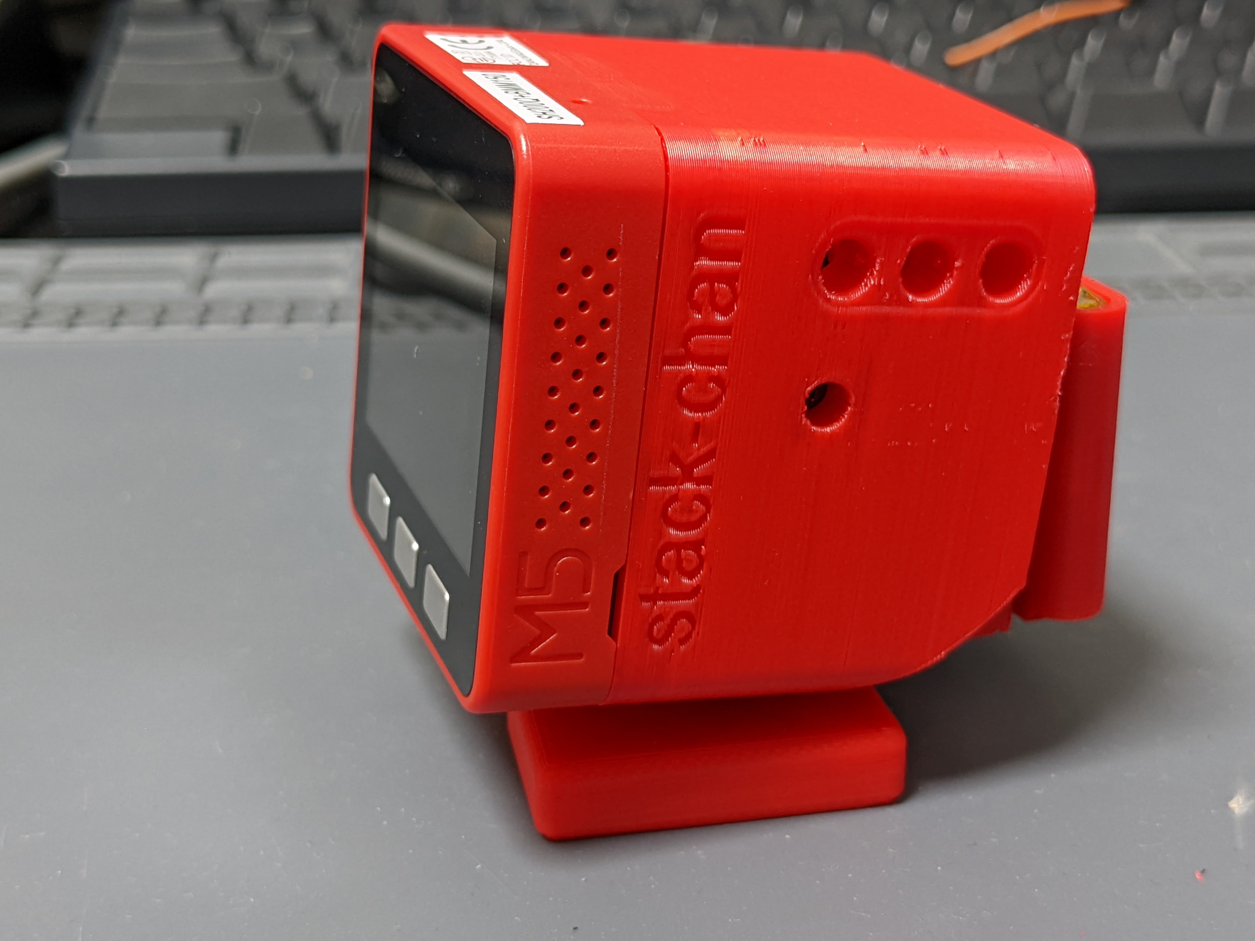
stack-chan
Stack-chan case v0
Currently the case data is developed with Fusion360.
The case is transitioning to the new specification (v1.0)
We are making a new case with improved compatibility.
- Case v0 (this document)
- PCB:
v0.2.1 - Servo motors: RX30X, SCS0009, SG90
- PCB:
- Case v1.0
- PCB:
v1.0 - Servo motors: XL330 (more to be added over time)
- PCB:
For the case with the latest specifications, please refer to the Stack-chan case v1.0 document
Editing
You can import and edit STEP files in each directory using any CAD software.
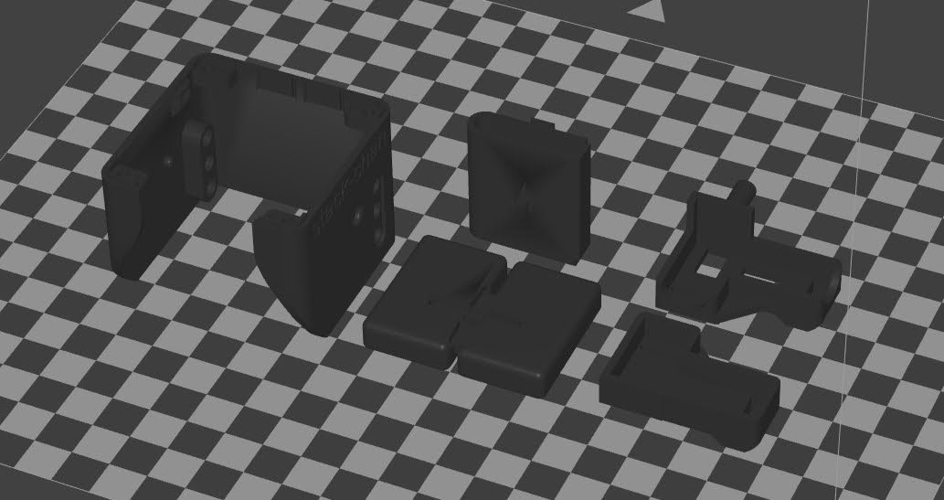
3D Printing
You can print STL files in each directory. The recommended orientation is below.
Assembly
Parts
- 3D-printed cases
- Shell
- Feet
- Bracket
- Battery backpack
- M5Stack Core Basic/Gray/Go/Fire
- Stack-chan board
- Two servos
- Currently available on:
- RS30X series(TTL version) serial servo
- SCS0009(TTL version) serial servo
- SG-90 pwm servo
- Currently available on:
- 3.7V Battery with PH 2-pin cable
- Screws
- M2 4mm * 4pcs
- M2 8mm * 2pcs
- (Optional) M3 15mm * 2本
Serial Servo Setup
Serial servos share a signal line. It’s necessary to specify ID for controlling each servo. Therefore, different IDs must be assigned in advance.
- ID1: Foot side (left-right rotation, pan axis)
- ID2: Face side (vertical rotation, tilt axis)
The serial servo driver has a command flashId to rewrite IDs](https://github.com/meganetaaan/moddable-scservo/blob/71292b9358353837a74ecea387cd3265a 610479f/src/scservo.ts#L274). A servo configuration tool using this command is under development.
About the angle of the servo
The angle of the servo mounting should be as follows.
- The center of the movable range is the reference angle (the angle when the stack chan faces forward).
- Install the servo so that the convex of the cross-shaped servo horn is aligned with the reference angle.
- If the servo is installed in the wrong direction, it will interfere with the stack chamber housing and will not operate properly.
- We recommend that you check the operation of the servo by writing the firmware once before fixing the servo to the case.
- The movable range and reference angle are different for each servo type (see the following table).
| Servo | Movable range | Reference angle |
|---|---|---|
| SG-90 | 0~180 degrees | 90 degrees |
| RS30X | -150~150 degrees | 0 degrees |
| SCS0009 | 0~200 degrees | 100 degrees |
Set up SCS0009 with GUI
Set up the following settings using Feetech’s official GUI tool.
- Change the ID of the servo
- Change the angle of the servo to the reference angle
In addition to the SCS0009, the following items are required.
- URT1
-
6-9V power supply
- Download the GUI debugging tools from Feetech’s repository on gitee.
- Connect URT1
- “DC6V-9V”…Power supply
- “USB”…PC via microUSB cable
- “G V1 S”…SCS0009 (Connecting multiple servos with the same ID will not work properly)
- Open
FD.exe - Select the COM port that URT1 is connected to, and select “Connect” without changing other values from default.
- Select “Scan”
- Select the servo connected to the URT1 as shown in the lower left corner of the screen.
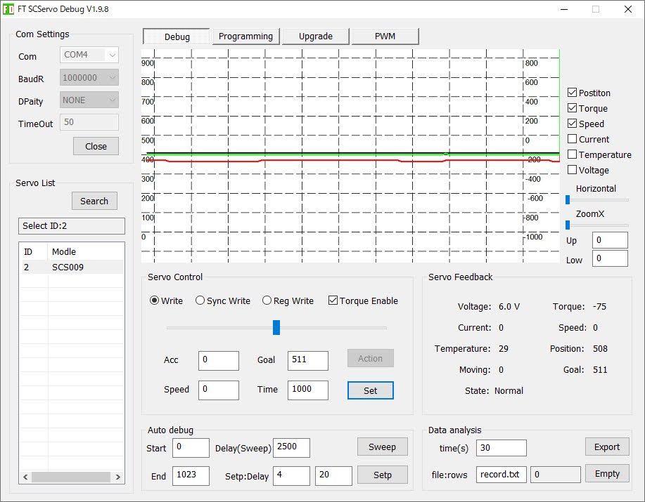
- Set the value of “Goal” to 511 and select “Set”
- The servo rotate to the reference angle
- If you change the servo’s ID, Open the “Programming” tab
- Select the “ID” row, change the value and select “Save”.
- The ID is rewritten.
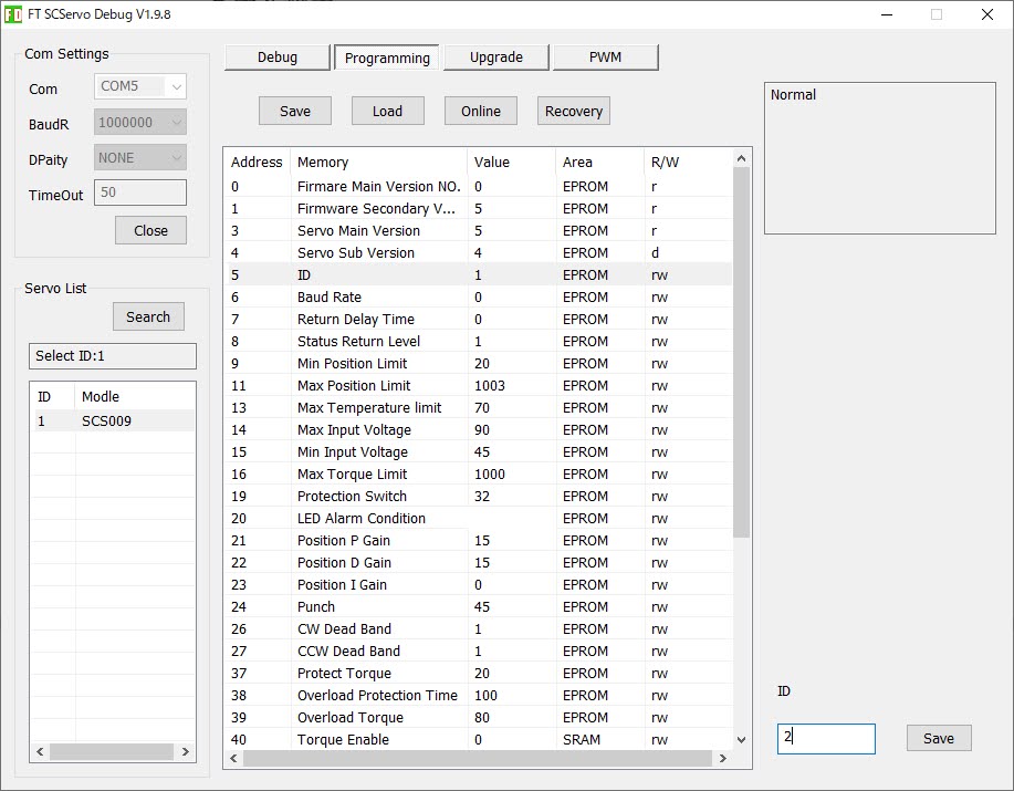
Note: If you select “Recovery”, the servo will not work properly.
How to Assemble
(Here are the steps with RS304MD servo. SG-90 and SCS0009 is similar to them)
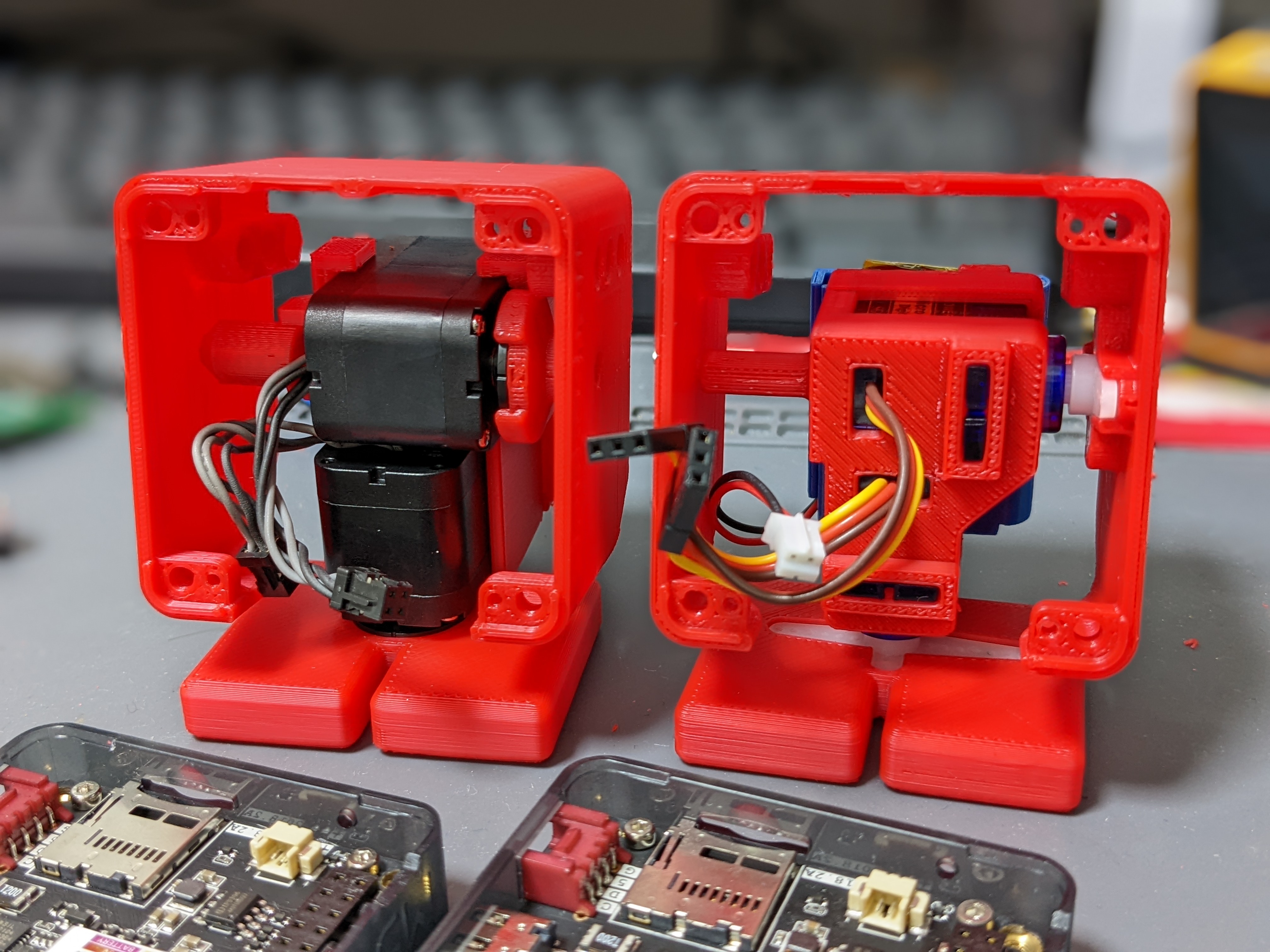
Bracket and Battery backpack
- Snap two servos into the bracket.
- Insert battery into the backpack.
- Insert the battery pack into the bracket by hooking the claws.
Shell and Feet
- Fix feet and shell with screws(M2-8mm * 1pc for each of them).
M5Stack and board
- Connect servo and battery cables to the board. Double check the direction of each connector is correct.
- For serial servos, the servo with ID: 1 is for the foot side (pan axis) and the servo with ID: 2 is for the face side (tilt axis).
For SCS0009, The signal line (white cable) is connected to write the pin.
- Fix the board on the robot with screws(M2-4mm * 4pcs)
- Stack M5Stack on the robot.
- If you want to fix the M5Stack, use the two holes below to screw(M3-15mm * 2pcs) it in place.